TurboCase is a command line utility that converts a KiCad PCB file into an OpenSCAD model. It will
automatically extract information about MountingHole footprints and place plastic posts underneath the PCB
to fit threaded metal inserts after 3D printing.
The case can be customized by adding special footprints from the TurboCase library to define extra cutouts
for connectors and a third dimension can be added to existing footprints by adding a Height
property to existing footprints.
A summary of the current features:
-
Generate a case from the shape defined on the User.6 layer including holes for the bottom of the case.
-
Generate a lid that fits on the case automatically. Holes defined in the User.7 layer will be cut out of
the lid.
-
Generate mounting posts in the case that line up with the MountingHole footprints on the PCB.
-
Add bounding boxes for any footprint on the PCB that has a Height property defined (shown in red above).
-
Automatically cut out the bounding boxes for those footprints from the case when clipping the walls.
- Generate a matching lid for the case based on a few preset shapes.
Getting started
TurboCase can run anywhere Python can run. The most generic way to install it is by pulling it from PyPI
$ pip install turbocase
For ArchLinux it is available in the AUR as turbocase
Designing
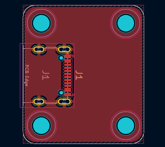
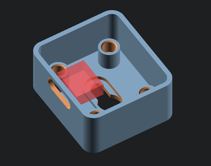
As design example we'll be using this simple PCB with only 4 mounting holes and a USB-C connector.
The shape on the Edge.Cuts layer will be used by TurboCase to generate a placeholder PCB in
the final OpenSCAD file to visualize the case. This shape will not be used for any of the case
generation code though.
The mounting holes are from the standard KiCad MountingHoles library. TurboCase will
determine
the screw size from the size of the drill hole in the footprint, or if no drill hole is present it will
use the circle shape from the F.CrtYd layer as fallback.
Case outline
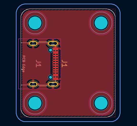
The first step is drawing the shape of the case. On the User.6 layer you can draw any shape
you want and it will be used as the shape of the inside of the generated case.
The shape on this layer follows the same semantics as the Edge.Cuts drawing for the PCB
outline. Any holes drawn into the case shape will be holes in the bottom of the case in the final
OpenSCAD file.
By default the wall thickness of the generated case is 1.2mm outside of the drawn case outline shape.
Holes for connectors
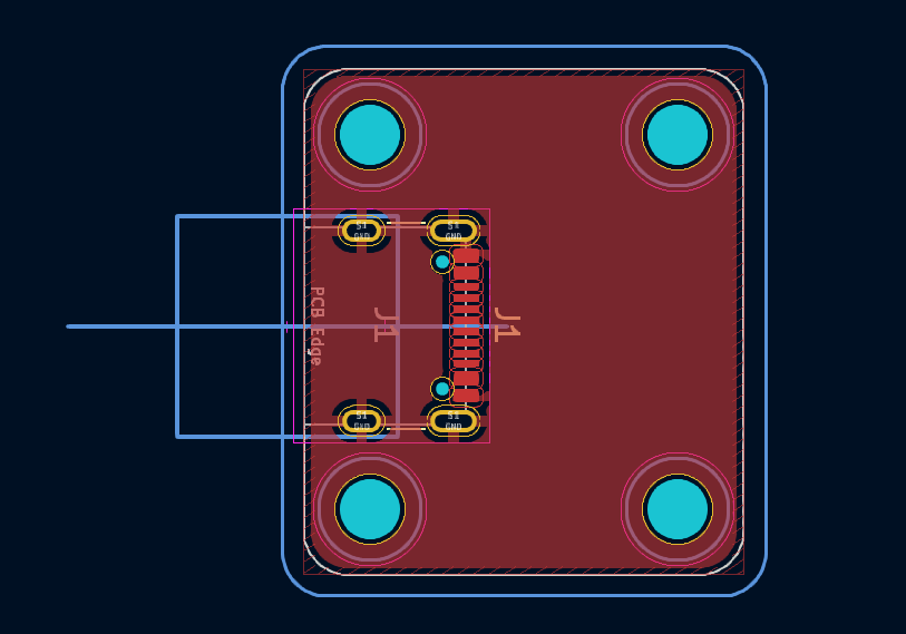
To be able to actually plug in a cable into that USB-C connector a hole is needed on the side. There are
two ways to add holes to the side. The first one is using a cutout shape from the TurboCase KiCad
library. There is one for the USB-C hole here named TurboCase:Cutout_TypeC. This will add a
USB plug shape to OpenSCAD that will be substracted from the case wall. The line in the footprint shows
the axis which will be used for cutting the shape.
The final OpenSCAD file will have all the calculations to make the height of the USB-C hole match
exactly with the connector on the board and it does have a slight margin to compensate for rough 3D
prints.
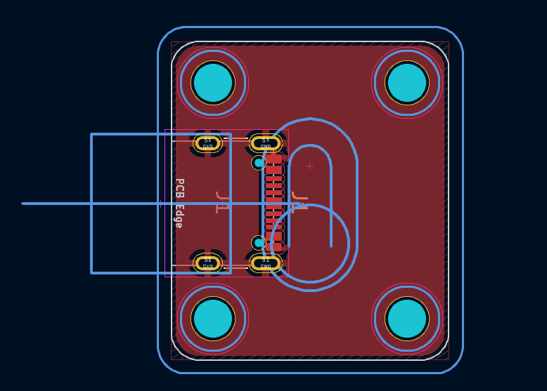
The second way is adding a Height property to the footprint of the connector in KiCad. This
will generate a cube with the size of the bounding box of the F.Fab layer of the footprint
and the height of the property. This shape will then also be extracted from the case walls. This method
only works for connectors that hang significantly over the PCB edge and are rectangular-ish. This method
is used for the RJ12 connectors in the header image.
The footprints with a Height property will also be visible as red cubes in OpenSCAD to
visualize where those connectors are, even if they don't cross a wall and actually create a cutout.
Prefabs
Normally just having a box with a few holes isn't enough. TurboCase has a library of prefabs available
in order to avoid spending a lot of time implementing common case features.
Some examples of this includes nice countersunk screw points in the bottom of the case to wall-mount the
case. Or even a keyhole screw mount like the image beside here to be able to slide the case on a wall
mount.
There is also a few more structural features available like battery holders and mounting posts for
screwing in the lid on the case.
Generating the case
The next step is actually making the case file. For this run the TurboCase tool:
$ turbocase -v example.kicad_pcb example.scad
[INFO    ] main    - Loading pcb from "example.kicad_pcb"
[INFO    ] main    - Using case drawing from layer [User.6] and lid features from [User.7]
[INFO    ] main    - PCB loaded
[INFO    ] main    -    Case size:         24.40000399999999mm x 27.40000399999999mm
[INFO    ] main    -    Mounting holes:    4
[INFO    ] main    -    Parts with height: 1
[INFO    ] main    -    Case prefabs:      2
[INFO    ] main    -    Insert sizes:      M2.5
[INFO    ] main    - Generating output at "example.scad"
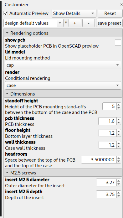
This .scad file can then be loaded into OpenSCAD to modify the settings and generate the final STL
files for 3D printing. The customizer sidebar in OpenSCAD might be hidden by default but can be shown by
enabling it from the Window menu.
The rendering options allow selecting what will be visible in the viewport. The PCB placeholder can be
shown here but it will never be included in the rendered STL file. The lid model setting
allows selecting which method is used to mount the lid on the case.
The render option sets the visibility of the case and the lid. The all option
is for visualizing how the case connects together but the individual case and
lid options are for actually generating the STL to 3D print as two seperate parts.
In the dimensions section the various size options can be adjusted like the default 5mm height between
the bottom of the case and the PCB. The Headroom defines the height of the PCB and is
automatically generated from the height of the tallest prefab or connector cutout.
For every detected screw size a screw section will be added to customize how those are printed. By
adjusting the values here the printed holes can be matched perfectly to the size of threaded metal
inserts to melt into the case after printing.
Source code
The official repositories for this project
are https://sr.ht/~martijnbraam/turbocase/
and https://codeberg.org/MartijnBraam/TurboCase.
Patches can be sent to Codeberg as a pull request or to sr.ht using git-send-email:
$ git config sendemail.to "~martijnbraam/public-inbox@lists.sr.ht"
$ git send-email HEAD^
If you'd like to support development of this project and several others like this financially consider
contributing to
my Liberapay or Patreon.